You've put together your model, and you're eager to generate those stunning stress contour plots that will impress your boss and the client. But hold on a moment! Let's make sure your model is correct!
4 steps to ensure quality in your finite element models
Before getting into mesh convergence studies or material sensitivity analyses, it's important to have a solid understanding of your model. That may sound a bit vague, but it's fundamental.
Quite often this basic step is overlooked. We get lost on those colorful contour plots. How can they be wrong? They're beautiful! Well, they can easily be both beautiful and wrong.
Failing to fully understand the models we create often leads to costly design problems, as we'll see later.
Ideally, we should be able to anticipate the shape of the deformation and the flow of stress in our models before even running any simulation. However, this level of intuition comes with experience. Here's a concise list of four basic steps that anyone, from students to senior engineers, can follow to ensure their models are robustly constructed.
Check boundary conditions
The first essential step in ensuring the quality of your model is to validate the boundary conditions. The displacements at the boundaries must be precisely zero, or as per your defined values. It may sound obvious, but it's easy to overlook something in complex models.
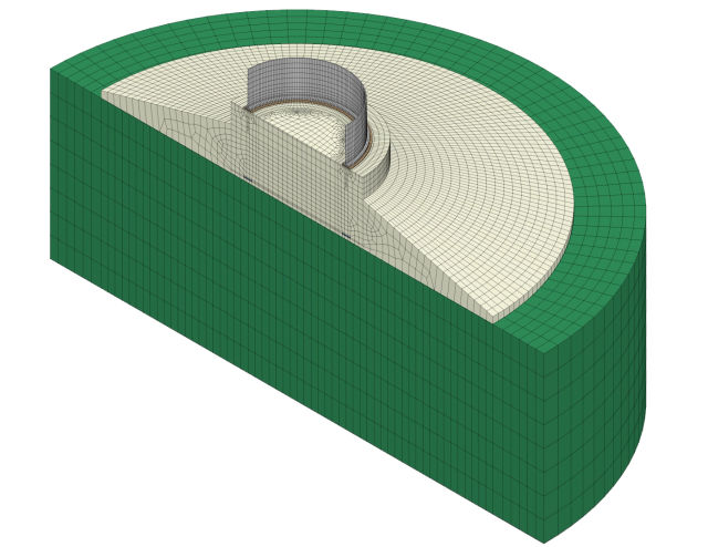
Let's look at an example. Suppose you are modeling a foundation for an onshore wind turbine. You've used volume elements for the slab, pedestal, and anchor cage, along with beam elements for the anchor bolts. You've also simplified the system by modeling just half of the foundation due to symmetry.

The horizontal displacements at the central cross-section should be zero, right? But wait, did you remember to select nodes of the bolts in the symmetry when applying the boundary conditions?
If you missed that, the bolts are moving freely perpendicular to the cross-section, which means they are not properly constrained. You'll want to go back and rectify this before rerunning the simulation.
Check reaction forces
The second step to check your model quality is to verify the reaction forces.
With your applied loads and boundary conditions in place, take a quick glance to confirm the signs of the reaction forces. Sometimes, you can do this without any complex calculations, just a simple visual check.
For instance, if you're applying a downward load on a beam that's fxied at both ends, you'd naturally expect the reaction forces at the supports to act upward, wouldn't you? If your simulation results show something different, it's a red flag indicating a potential modeling error.
The next step involves creating a simplified free body diagram and performing calculations to determine the reaction forces. These calculated values should align with what you obtained in your simulation.
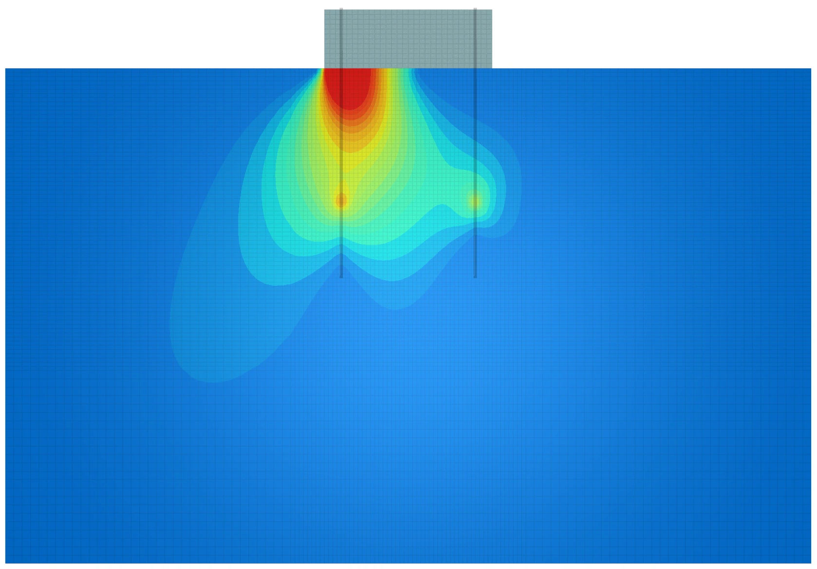
Let's look at another example. Suppose you're modeling a wind turbine foundation with the ground as solid elements. The ground acts like a flexible boundary condition for the foundation slab. Here, you can sum up the nodal forces at the slab-ground interface and compute the moment contributions at the foundation center.

These calculated values can be directly compared to the manual calculations of resultant force and moment at the slab's base. If they don't match, it's a signal to revisit your applied loads and boundary conditions.
Check contact surfaces
The third step to check your model quality is to inspect the contact surfaces. These contact surfaces define how two structural elements interact. Are they bonded and move together? Is sliding permitted? Can they separate? All of this needs to be crystal clear before you even open your FEM software to build your model. And after your model is ready, you need to ensure that these contact surfaces behave exactly as you expected.
Sometimes, the assumptions you initially made might not hold true. But after running an initial simulation and scrutinizing deformations, stress distribution, and contact behavior, you should be able to spot any discrepancies and rectify them.
In my experience, most of the issues with complex finite element models come from these contact surfaces. Let me share an example from a large wind project I once reviewed. This big project, with a budget well over 100 million euros, involved the structural verification of wind turbine foundations with a non-usual tower-foundation connection.
The designer had created a very detailed 3D finite element model to assist in making design decisions. Then, he produced an extensive calculation report with the results. However, he failed to fully understand his model, so all that work was wasted.
The tower was made of steel and the foundation made of concrete. The tower base flange was embedded a few centimeters into the concrete and anchored with preloaded bolts. One of the problems with the model was that the contact surface between the steel element and the concrete pedestal was modeled as bonded.
That was ok as long as there was no loss of contact in the flange. But when gapping did occur, the friction between the lateral faces of the flange had to balance the pulling forces, and then the pedestal would be working in bending. Both consequences were problematic: the friction couldn't balance the large pulling forces from wind-induced overturning moments, and the pedestal was never designed to handle bending loads. The result? An undersized design.
By merely scrutinizing the behavior of the contact surfaces in the early stages, one could have recognized that the 'bonded' assumption was not quite accurate. So, once more, emphasize the importance of ensuring that the contact surfaces behave precisely as you anticipate.
This seemingly small error rendered the model stiffer than the actual foundation, leading to design revisions, project delays, and a rather costly mistake.
Compare nodal and element results
If your model has successfully passed the previous three checks, you're likely heading in the right direction.
The overall behavior of your model seems to be in good shape. Now, it's time to confirm that the materials can endure the stresses they're exposed to.
Stresses can be significantly influenced by the mesh shape and density. If the mesh is too coarse, your stress results might lack accuracy. On the other hand, if the mesh is too dense, you may need a supercomputer running for 24 hours to get the first results.
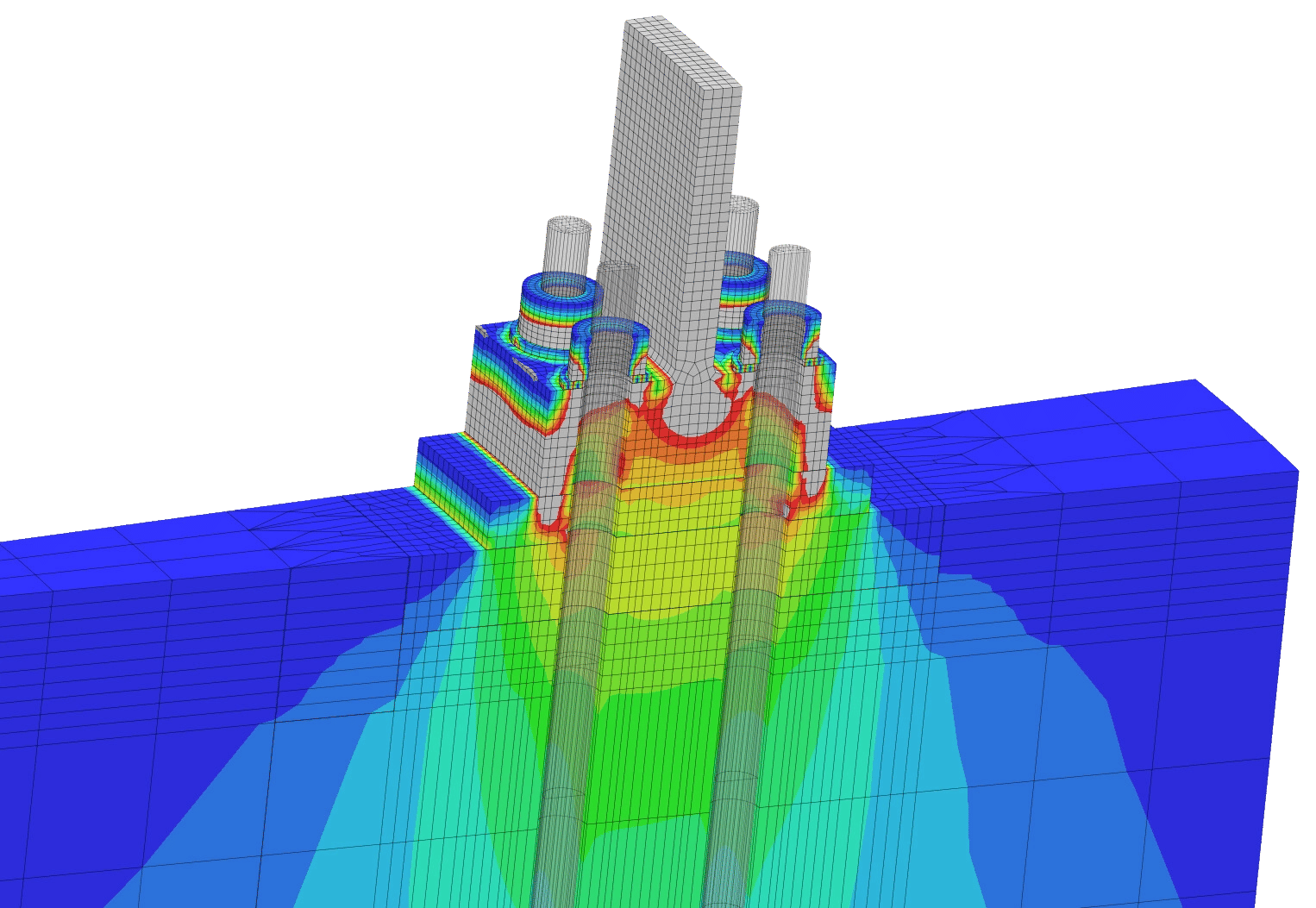
In the following plot, you can see the vertical nodal stress distribution within in an onshore wind turbine foundation model. The mesh beneath the tower base flange on the pedestal detailed enough to capture the actual stress distribution. As you reduce the mesh size, the stresses will converge, eliminating the need for further refinement to get accurate results.

Typically, it's advisable to start with a coarse mesh and incrementally refine it. You record stress levels at critical areas, and when the variation from the previous model isn't large (usually around 5%), it's generally considered acceptable. This practice is known as a mesh convergence study.
Here's a handy tip for identifying areas that may need a denser mesh: compare nodal and element stress plots. If the stress distribution and values align closely between the two, you're likely on the right track. If not, consider further refining the mesh in those specific areas.
That being said, not all models are built to perform exhaustive stress analyses. Sometimes, you may only need an estimate of stiffness or displacements that are not so heavily influenced by the mesh. In such cases, a coarser mesh may be enough for your purposes.
Conclusion
We've explored four fundamental and straightforward checks to ensure that our finite element models perform as expected. While specific scenarios may introduce nuances, these checks serve as a reliable general rule to ensure meaningful simulation results. To recap:
- Confirm the displacements at boundary conditions.
- Inspect reaction signs and cross-check with simple hand calculations.
- Scrutinize the status, sliding behavior, pressure distribution, and separation of contact surfaces to ensure they're appropriate.
- Conduct a comparison between element and nodal strain and stress contour plots. They should yield similar results, both in terms of distribution and values. If disparities arise, consider refining your mesh.
By following these steps, you're well on your way to building robust finite element models and obtaining trustworthy simulation outcomes.